|
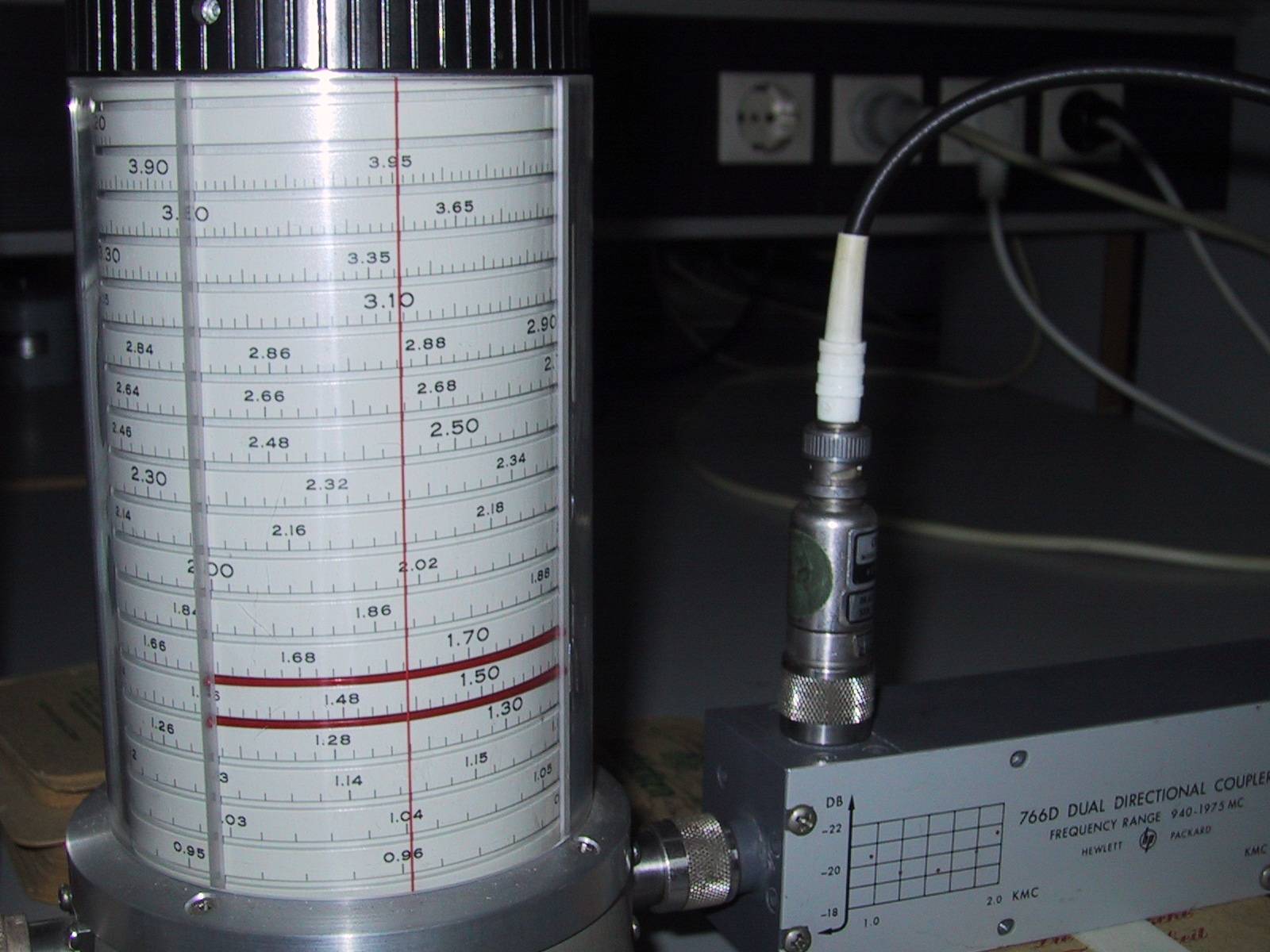
Experiment 1: Propagation of waves on coax cables and waveguides
In this introductory experiment you'll make yourself familiar with the
propagation of waves on double lines and waveguides, utilizing coxial and waveguide transmission lines as well as
bi-directional couplers. The determination of mismatches and their effects
are being investigated. Special emphasis is put on measuring absolute and
relative powers (the former with thermystors, the
latter with detector diodes.). This experiment is familiarize
the students with HF equipment such as wobblers, oscilloscopes, power and
frequency meters. Handling such devices is an indispensable prerequisite for
all subsequent experiments.
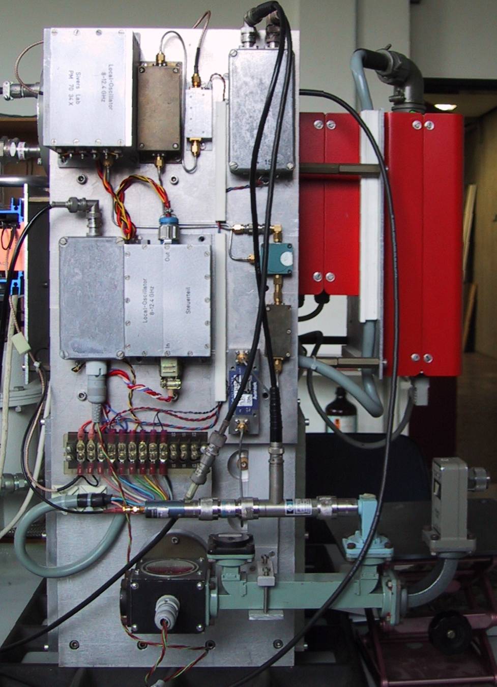
Experiment 2: Heterodyne receiver
The goal of this experiment is to set up a working radio-astronomical
heterodyne receiver. To this end, the necessary active and passive components
are studied in the first part of the experiment (amplifiers: gain, bandwidth;
mixer: mixing losses; filters: bandwidth, sideband rejection). Having determined
the components' characteristics, the next task is to construct an overall
concept for the receiver, including a level diagramme,
aiming at highest sensitivity and stability. The receiver is then built up
using the tested components. Its characteristics (i.e. sensitivity,
bandwidth, gain, linearity, stability) are determined. The experiment is complemented
by studying the properties of partially polarized waves, describing them via
the Stokes parameters. The analysis of such waves can be carried out using an
IF polarimeter as is generally done in radio
astronomy. The methods with which such a polarimter
is calibrated are shown. Both, CW as well
as coherent and incoherent noise signals are then
analyzed with the balanced polarimeter.
Experiment 3: Cooled Dicke system
This one is more like a demonstration experiment in which you have
ample opportunity to interact though. The aim is to make you familiar with
the performance a continuum receiver, whereby in particular the tremendous
effect on sensitivity by cooling active and passive components is shown. The
experiment teaches how the Dicke principle, i.e.
the continuous calibration of the amplification to improve the stability, is
realized by a phase-stable control of the Dicke
switch, by a phase- selective demodulation of the measured signal and by
computer supported combi- nation of individual
measuring periods. Since the backend used here can be found at most modern
single-dish telescopes this experiment is a good preparation for practical
continuum measurements.
Experiment 4: Observations with the Effelsberg
100-m telescope (special arrangement
required)
This, too, is more like a demonstration experiment, with active
participation of the students. The main telescope characteristics of the
100-m telescope are to be de- termined. Using radio
sources with known flux densities and the temperature of an internal
calibration signal, the aperture efficiency is derived. By cross-scanning a
point source, the telescope half-power beam width and the main-beam
efficiency are subsequently measured. Both, a point source as well as an
extended target are mapped thereafter (with all Stokes parameters), and maps
of the total and polarized radiation are produced. The results are discussed
in terms of angular resolution, telescope gain and sensitivity. Finally,
spectroscopic measurements are performed by observing radio recombination
lines in the Orion nebula. We usually carry out this experiment at 5 GHz, but
there is flexibility since we have a choice of receivers in the secondary
focus.
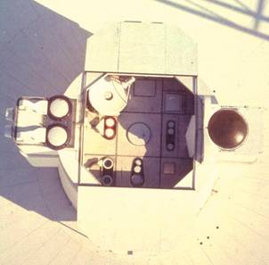
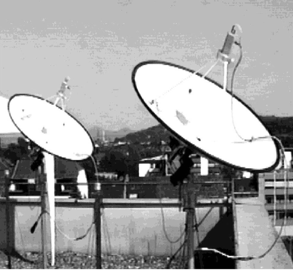
Experiment 5: Twin-element interferometer (currently out of order)
Using a twin interferometer on top of the Astronomical Institute, the
basic problems and performance of aperture synthesis are demonstrated. The
target of these observations, which are carried out at 11.5 GHz, is the
(quiet) sun. After measuring the characteristics (HPBW) of the individual
dishes we determine the fringe sepa- ration and
fringe frequency as a function of baseline (transit mode). The source
visibility is then measured as a function of hour angle (tracking mode), from
which the (one-dimensional) source structure can be computed via an FFT. The effect of fringe washing is shown and discussed.
|